- Description
- Function drawing
Function
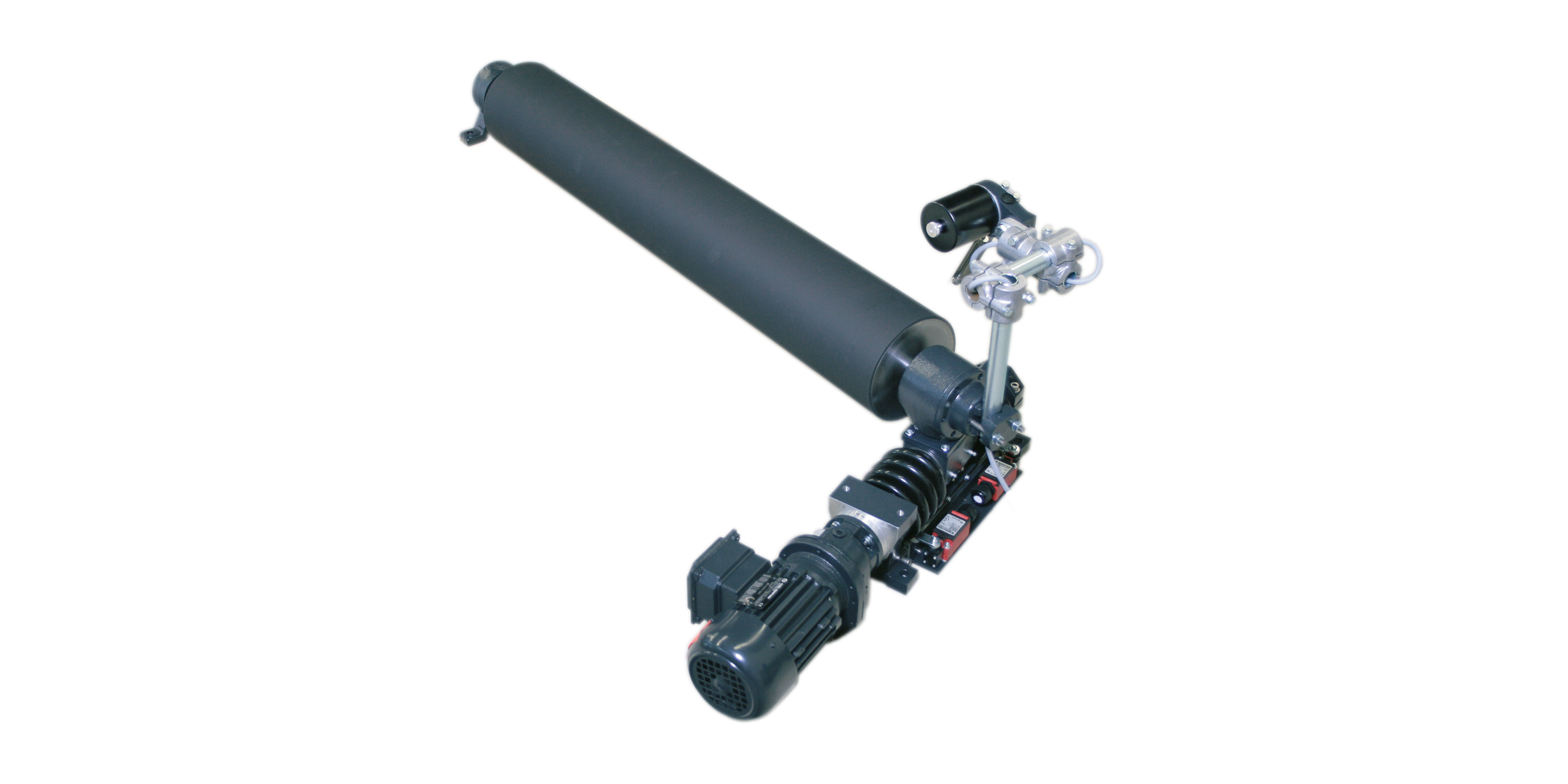
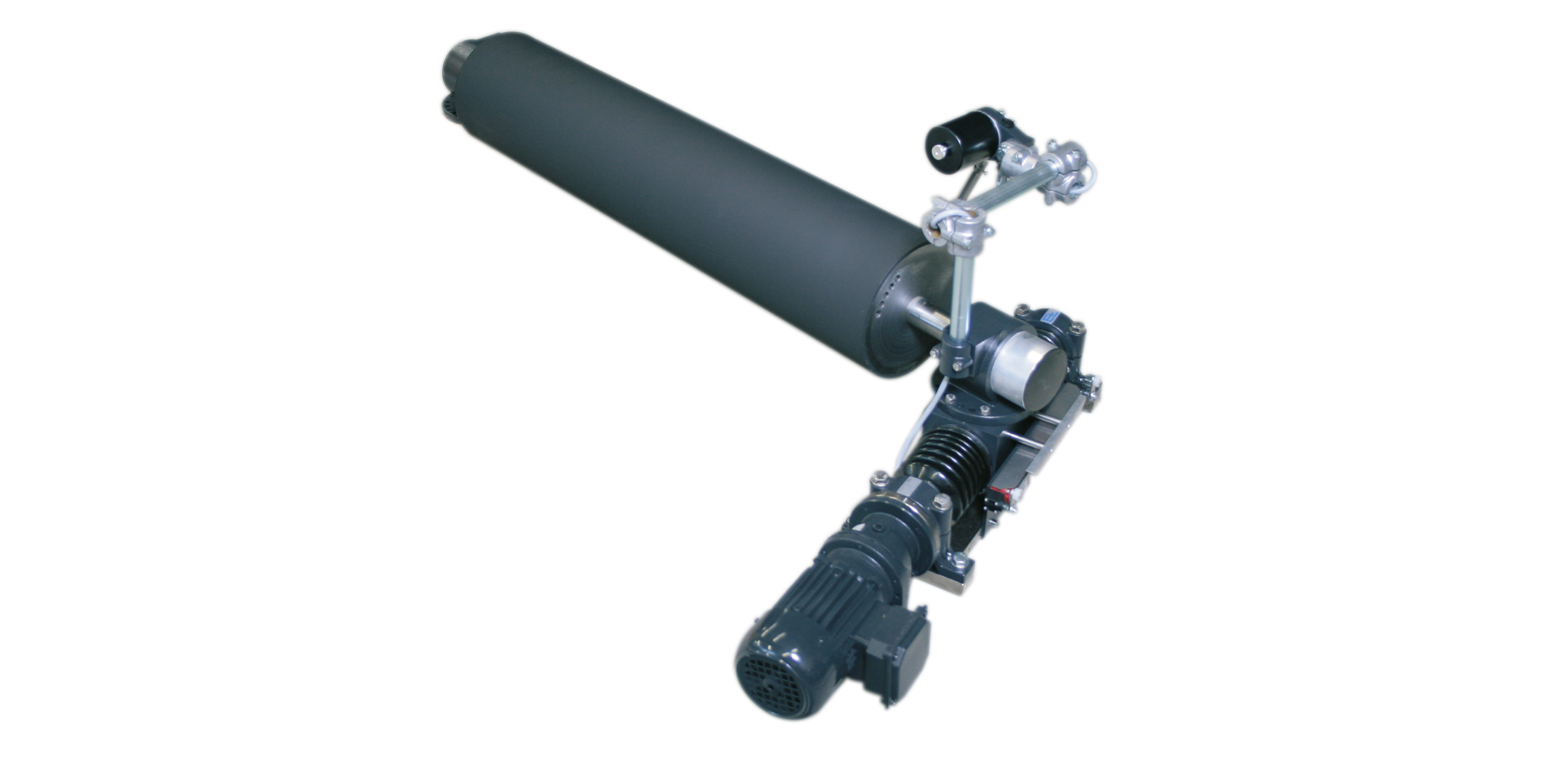
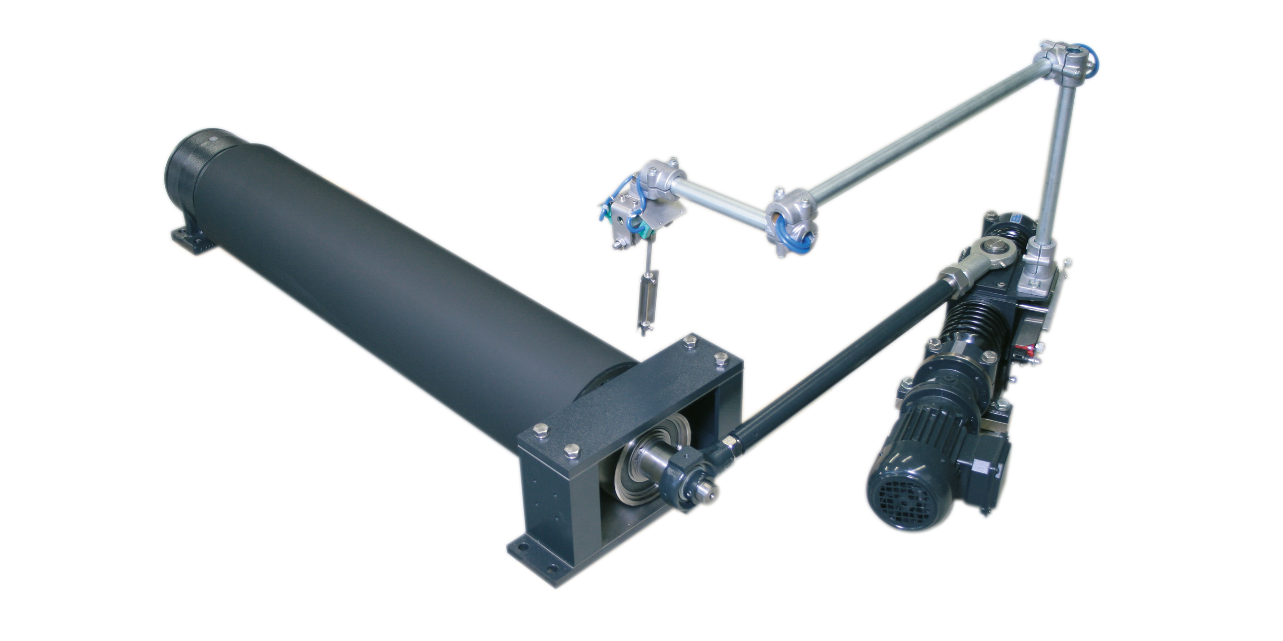
Rollers at an angle to the direction of belt travel cause the belt to move laterally. This principle is used by the pivoting roller systems ELBANDER. The pivot point for the pivoting roller is one of the two bearings at the ends. The positioning roller is positioned at an angle around this point, depending on the correction required.
Area of use
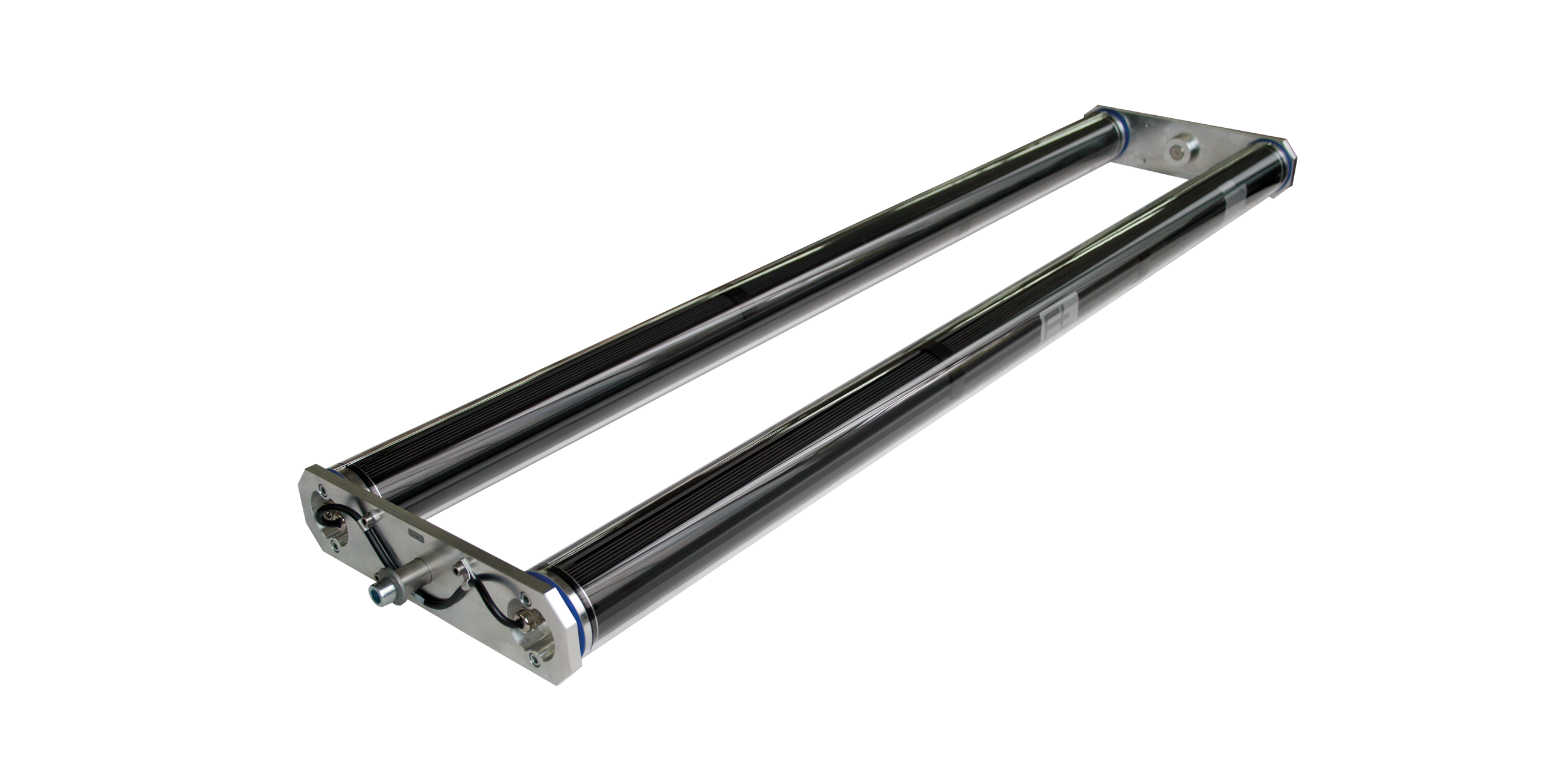
Pivoting roller systems are used to guide conveyor belts.
Application
On conveyor belts, the pivoting roller is mounted on the bottom run just ahead of the lock roller. The actuator is to be arranged parallel to the direction of travel of the belt. The actuating movement must be at the bisector between the infeed and exit path. The infeed path should be the equivalent of at least one web width. The exit path is to be kept as short as possible. The wrapping around the positioning roller should be between 40° and 60°. For production speeds >1000 m/min the wrapping should be reduced to 10° to 20°. The position is acquired using an edge sensor immediately after the positioning roller. To prevent possible interference from the stretch roller on the control system, this roller is only allowed to be positioned with its axis parallel.
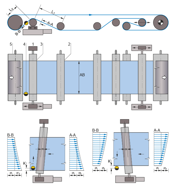
Legend
A-A = Belt tension distribution at the infeed | B-B = Belt tension distribution at the outfeed | K = Correction of the belt position | σ = Correction angle | σ1 = Basic belt tension | σ2 = Tension distribution on actuating movement to left | σ3 = Tension distribution on actuating movement to right | 1 = Pivot point | 2 = Infeed roller | 3 = Positioning roller | 4 = Sensor | 5 = Locking roller | L1 = Infeed path | L2 = Exit path | AB = Operating width
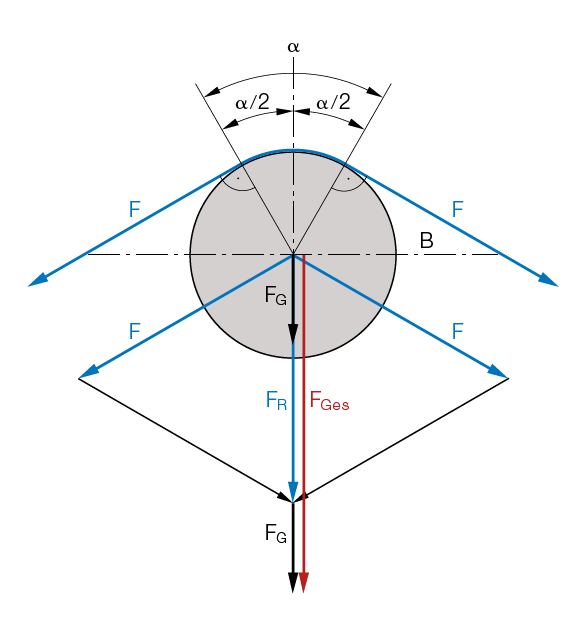
Legend
B = Movement plane of positioning roller | F = Belt tension | a = Wrap angle | FR = Resulting fabric tension | FG = Weight of the positioning roller | FGes = Total force| FGes/2 = Force per bearing side
Calculation of bearing force
FTot/2 = (FR + FG)/2


