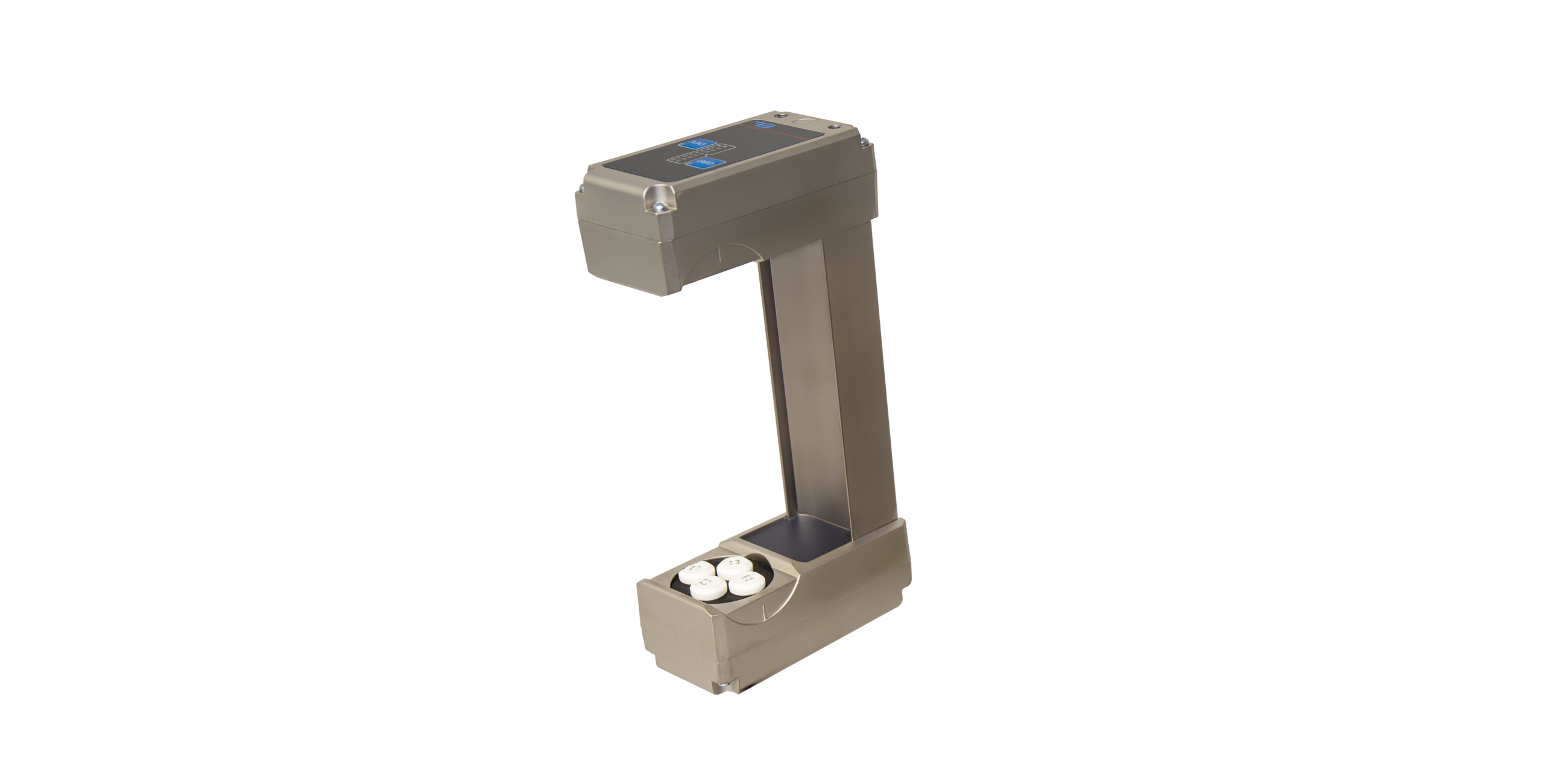
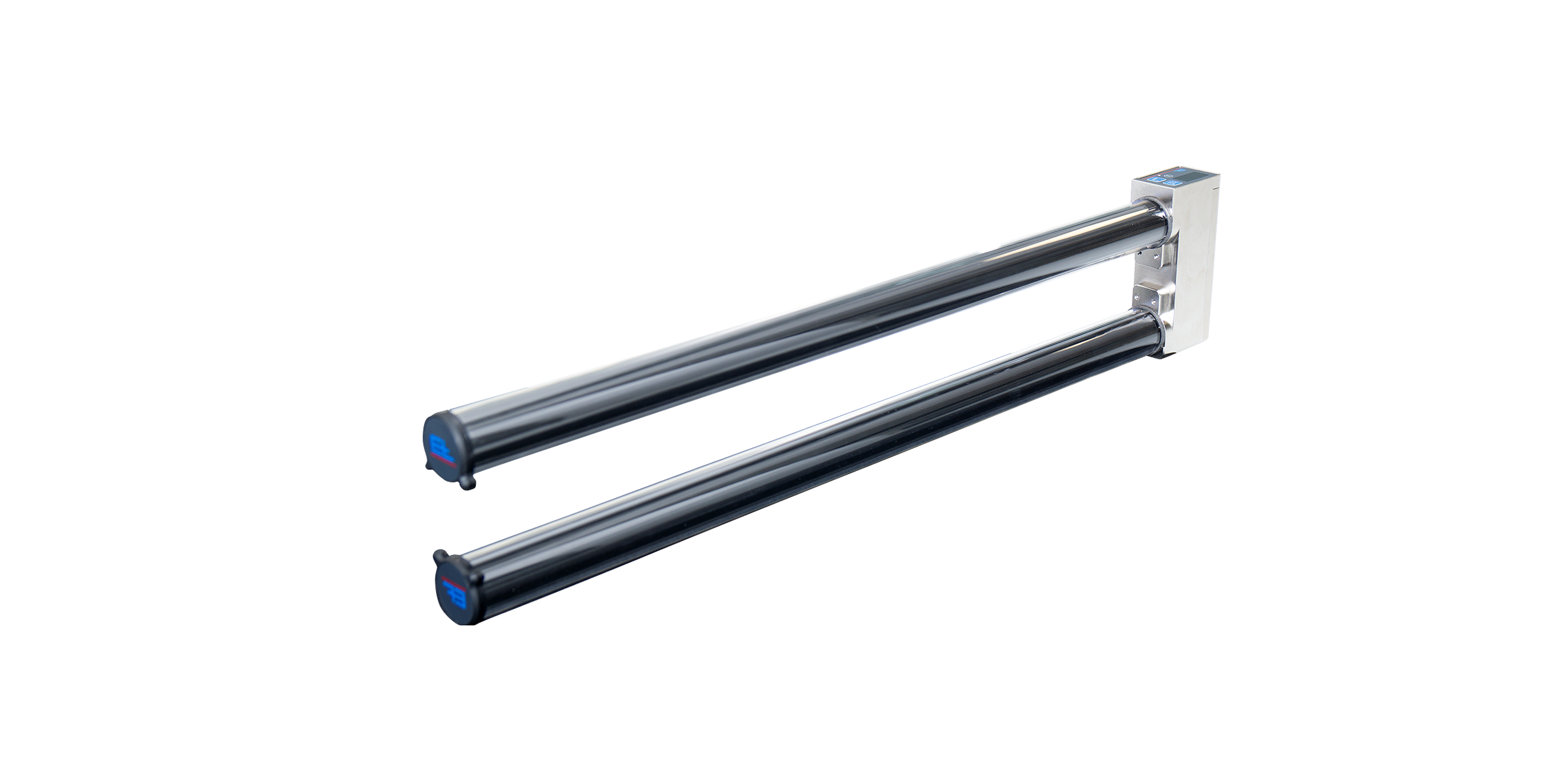
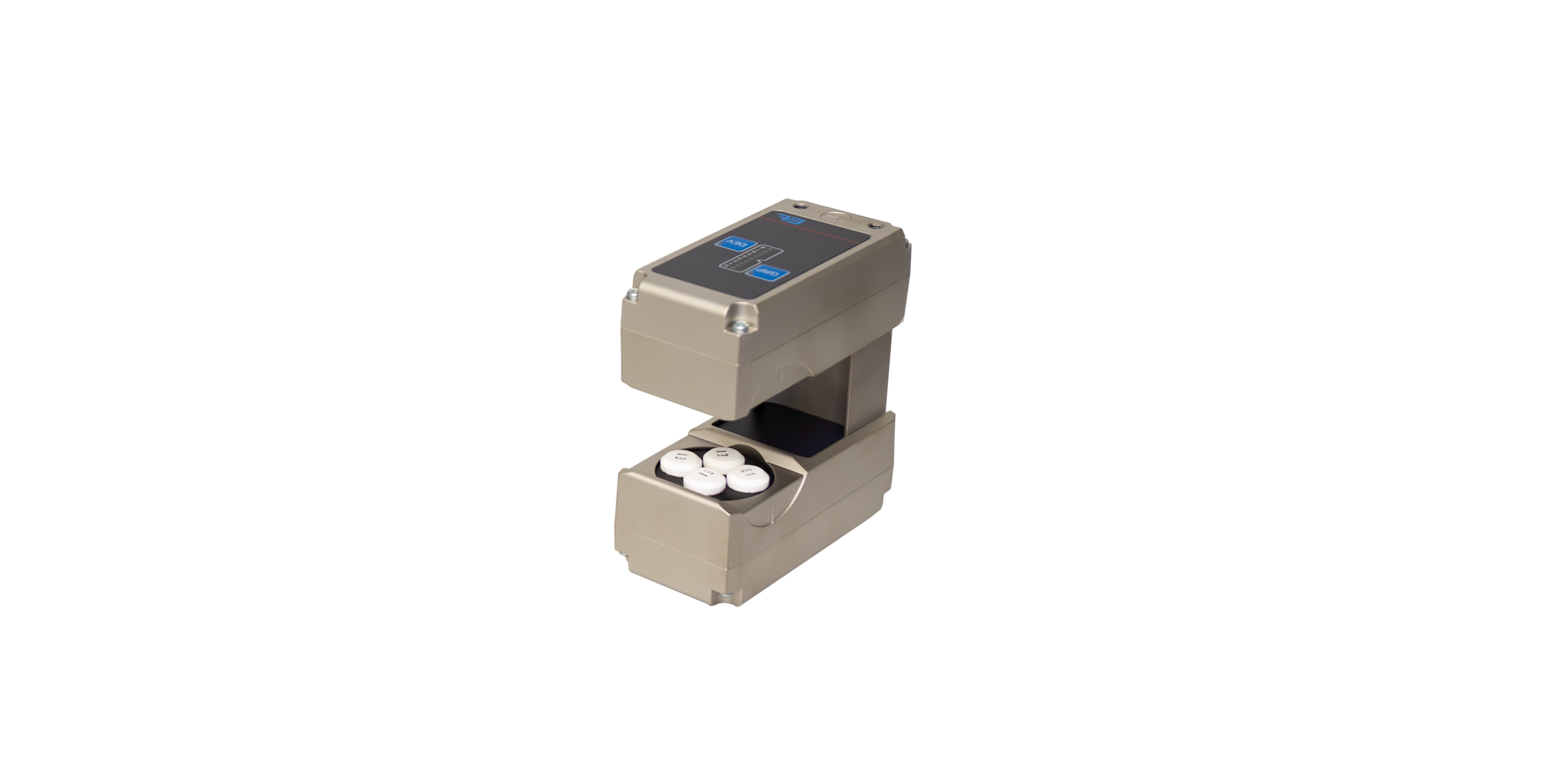
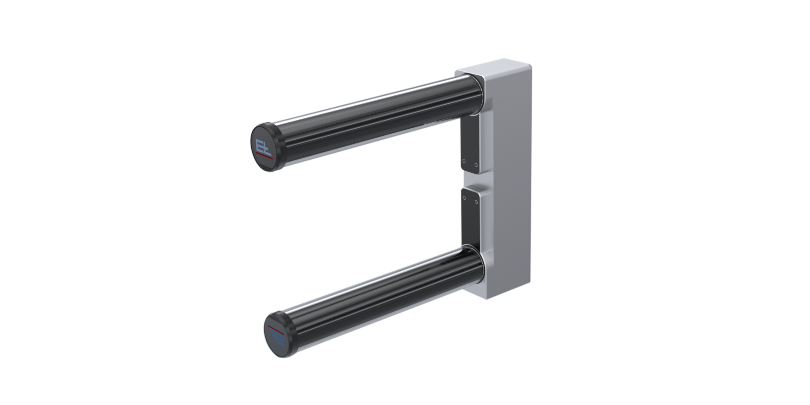
- Description
- Function drawing
Function
Web guiding with ELTURNER turning bar systems is based on a simple principle: A bar is mounted at an angle of 45° to the longitudinal and transverse axes while the web runs over it with 180° wrapping. This has the immediate effect of changing the direction of web travel by 90°. To correct the web position at the same time, the turning bar is moved parallel to the infeed plane according to the actuating signal, thus offsetting the web to the side as it runs off.
Area of use
Use of a pivoting frame system in combination with turning bars is recommended in cases where the web needs to be turned and fed to the next process with high precision.
Application
The greater the web tension, the modulus of elasticity and the required correction, the longer the infeed, exit and transfer paths should be designed. Experience has shown that these paths should be the equivalent of 60 to 100% of the web width. The sensor should be positioned behind the positioning roller, as near to it as possible.
Legend
A = Web tension distribution at infeed | B = Web tension distribution at outfeed | K = Correction of the web guiding | a = Correction angle | σ1 = Basic web tension | σ2 = Tension distribution through actuating movement to left | σ3 = Tension distribution through actuating movement to right | 1 = Guide frame | 2 = Infeed roller | 3 = Turning bar | 4 = Sensor | 5 = Fixing roller | 6 = Pivot point | LÜ = Transfer length | L1 = Infeed path | L2 = Outfeed path | AB = Operating width


