- Description
- Function drawing
Function
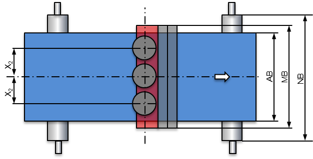
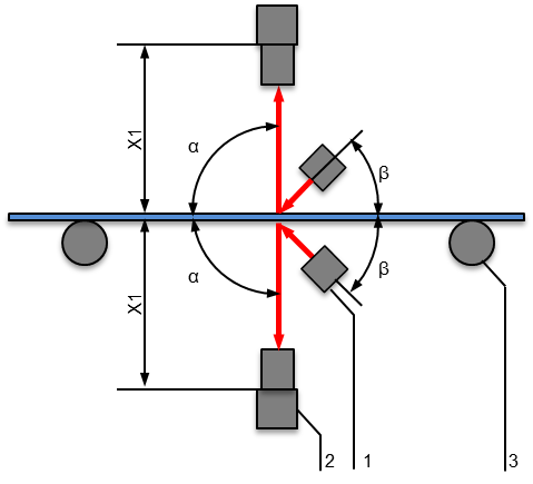
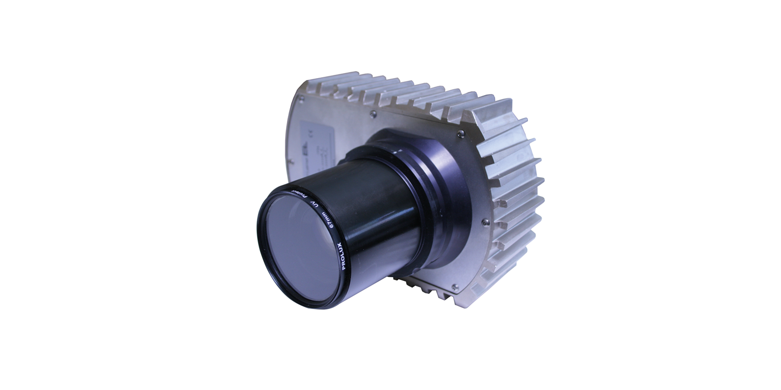
A row of OL 91 CCD cameras is mounted on both the front and rear side of the calendered materials. High-intensity LED lamps provide enough light to allow even smallest errors to be detected. The cameras continuously evaluate the surfaces; as an option, the fault data can be saved in a database for quality control purposes.
Area of use
Calender system in the tire industry
Application
In the textile cord or steel cord calender after calendering. To record the contrast, the cameras must be arranged according to the reflected light principle. The web must be run flat and may not show any height variants. 1 to 3 cameras can be used, depending on the web width and resolution.

Legend
AB = Operating width | MB = Measuring range | NB = Nominal width | X = Camera spacing | X1 = Spacing between web surface and cameras | X2 = Camera spacing | α = Angle between web surface and camera | b = Angle between web surface and light transmitter | 1 = Light transmitter | 2 = CCD line scan camera | 3 = Guide roller


