- Description
- Function drawing
Function
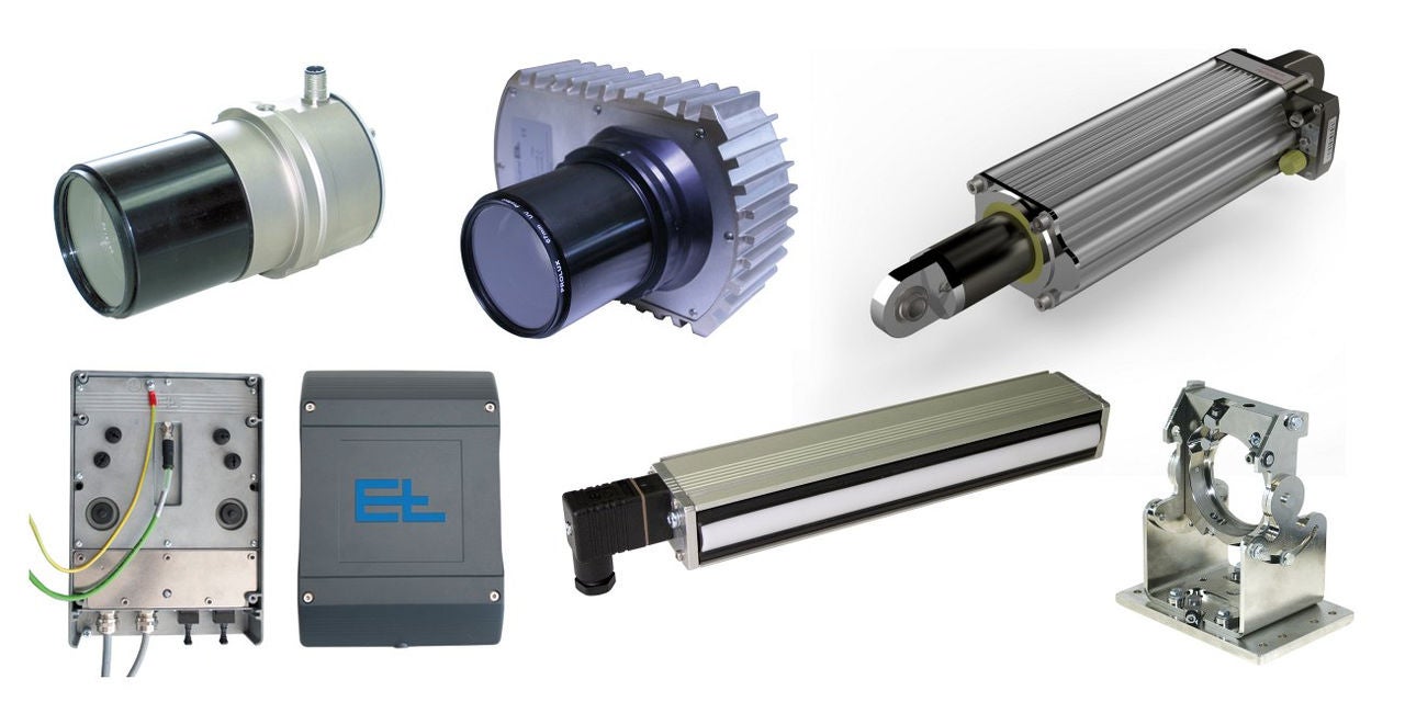
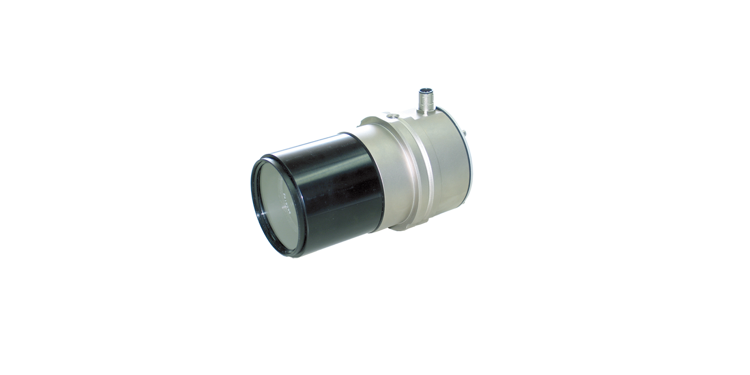
The belt (steel cord) is acquired with the aid of CCD cameras, infrared sensors or laser triangulation sensors. The sensors scan the gap between the two conveyors. The conveyor before the camera (viewed in the direction of transport) can be moved laterally, i.e. at an angle of 90° to the material transport direction, with the aid of an actuator (AG 9), to control the material. The conveyor after the camera or tire building drum locks the material controlled.
Area of use
The belt control system is used in tire building machines and controls the steel belt before the tire building drum.
Application
As soon as the camera detects the tip of the material, the conveyor is stopped and aligned laterally to suit the position of the material. Then, during further transport, the material is controlled in the area of the angled cut edge either by the outer edge or the cut edge itself. In the area without a cut edge, the control mode switches to "by center of material". The angled edge at the end of the material is then again controlled by an outer edge or the cut edge. Control by the cut edge is used mostly for wider materials (e.g. truck tires), as the cut edges may no longer be straight here due to tensions in the material and therefore gaps (poor splice) could potentially arise on the drum during control by the material edge.
Legend
K = Web correction | α = Angle of cut edge | AB = Operating width | MB = Measuring range | BB = Belt width | NB = Nominal width | L1 = Length of belt | L2 = Length of cut edge
1 = CCD line scan camera | 2= Infeed rollers | 3 = Conveyor belt | 4 = Light transmitter | 5 = Fixing conveyor belt | 6 = Actuating drive | 7 = Incremental encoder

Belt guiding – standard

Belt guiding – by cut edge


