- Description
- Function drawing
Function
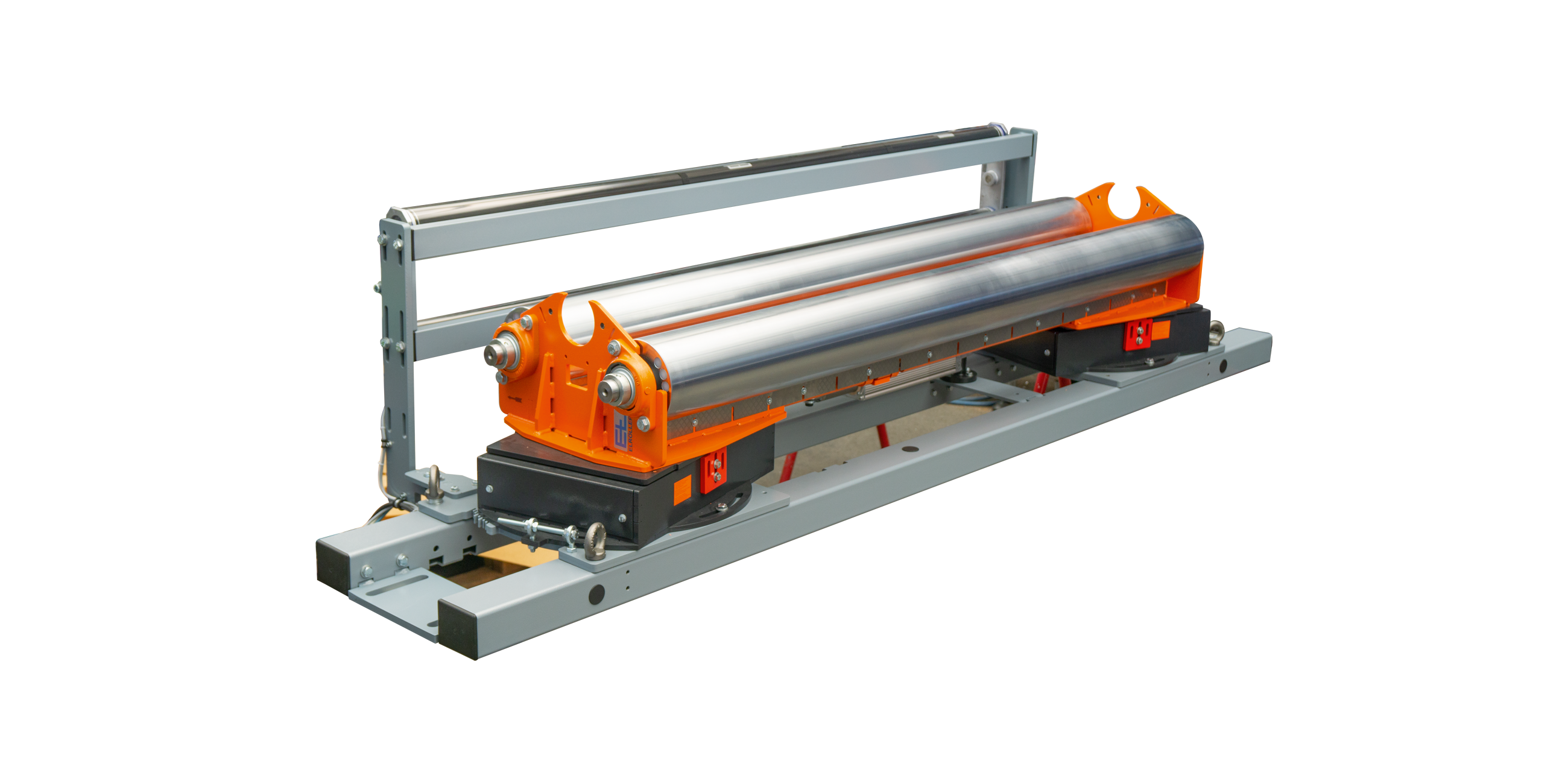
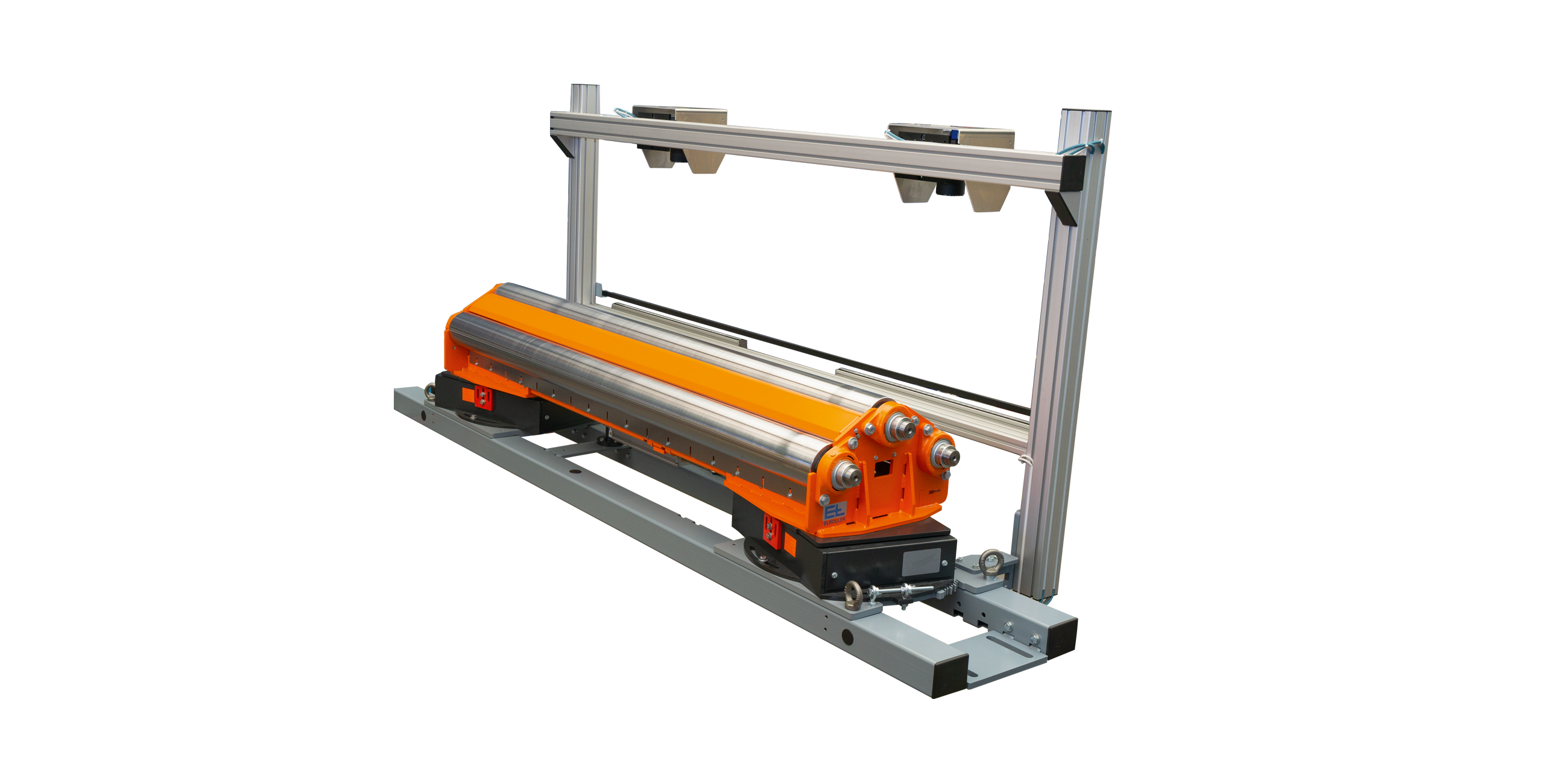
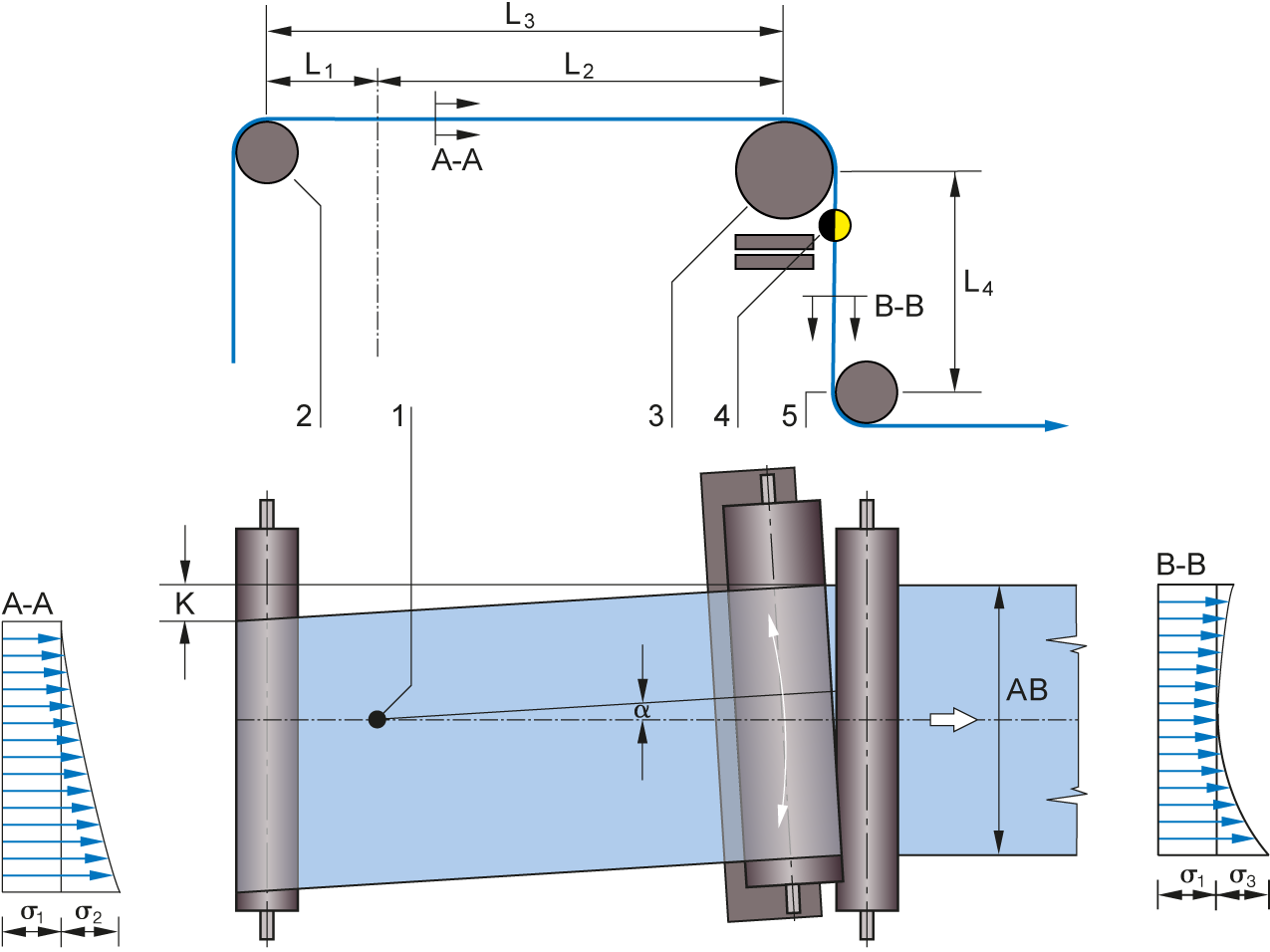
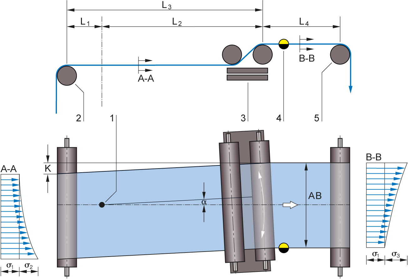
ELROLLER steering roller systems correct the web position already in the infeed plane. They consist of a fixed base frame and a moving guide frame. The latter accommodates one or two positioning rollers and swivels around an imaginary pivot point in the infeed plane. The pivot point should, on the one hand, be far enough away from the infeed roller to ensure the web correction does not influence the infeed roller. On the other hand, it must be far enough away from the positioning roller to ensure the elasticity of the web is fully exploited but not overstrained. A steering roller is termed a proportional actuator. It must therefore operate in a friction-locked manner and must not permit any sliding between the web and the positioning roller.
Area of use
ELROLLER systems are always used where there is a long infeed path for process-related reasons.
Application
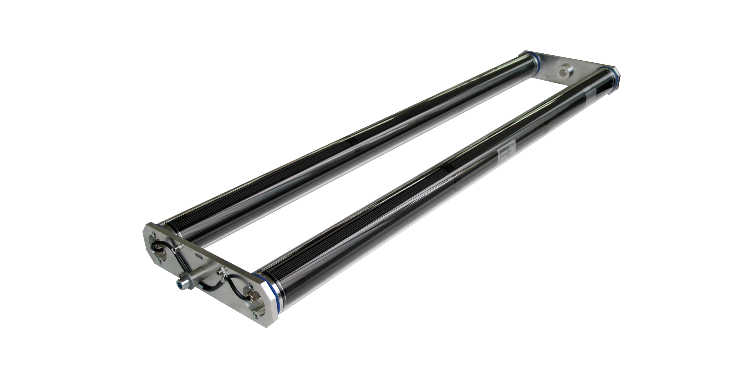
Depending on the space available, steering rollers may be fitted with one or two positioning rollers. On versions with one positioning roller, the web is guided with wrapping of 90°. On versions with two positioning rollers, less wrapping is possible. In this case, the web runs in almost the same plane as the outfeed roller.
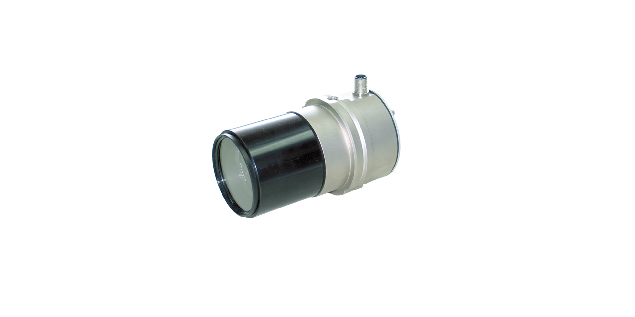
The following applies when mounting an ELROLLER: the infeed path should be the equivalent of two to three times the web width, the exit path should be the equivalent of between 50 and 100 percent of the web width. The sensor should be positioned behind the positioning roller, as near to it as possible. As a consequence, improved control dynamics are achieved thanks to the resulting short response time.
Legend
A-A = Web tension distribution at infeed | B-B = Web tension distribution at exit | K = Web correction | a = Correction angle | σ1 = Basic web tension | σ2 = Tension distribution due to pivoting movement of roller frame at the infeed | σ3 = Tension distribution due to pivoting movement of roller frame at the exit | 1 = Pivot point | 2 = Infeed roller | 3 = Positioning roller(s) | 4 = Sensor | 5 = Locking roller | L1 = Infeed path to the pivot point | L2 = Infeed path to the steering roller | L3 = Infeed path | L4 = Exit path


