- Description
- Function drawing
Function
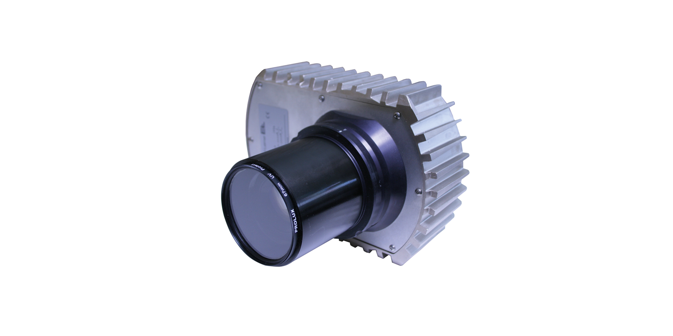
The tread is acquired using a CCD camera or a laser triangulation sensor. The sensor scans the material optionally before the conveyor or in the gap between the conveyor and the tire building drum. The conveyor before the camera (viewed in the direction of transport) can be moved laterally, i.e. at an angle of 90° to the material transport direction, with the aid of an actuator (AG 9), to control the material. The conveyor or the drum after the camera locks the material controlled.
Area of use
The tread control system is used in tire building machines and controls the tread before the tire building drum.
Application
Control can be by various criteria for the material, for example groove, ridge or total width. As soon as the camera detects the control criterion, the conveyor is aligned laterally to suit the position of the material. Depending on the position of the camera, the conveyor is stopped briefly for this purpose or the transport speed is temporarily reduced. Afterwards the material is adjusted to suit the control criterion while the material is transported onward. If a control criterion is no longer detected, control is automatic by the outer edges.
Legend
K = Web correction | AB = Operating width | MB = Measuring range | BB = Belt width | NB = Nominal width | L1 = Length of tread
1 = Light transmitter | 2= Infeed conveyor belt | 3 = Conveyor belt | 4 = CCD line scan camera | 5 = Fixing conveyor belt | 6 = Actuating drive | 7 = Incremental encoder | 8 = Lane search area dependent on: 8.1 – Outer edges; 8.2 – Inner edges
Tread control system


