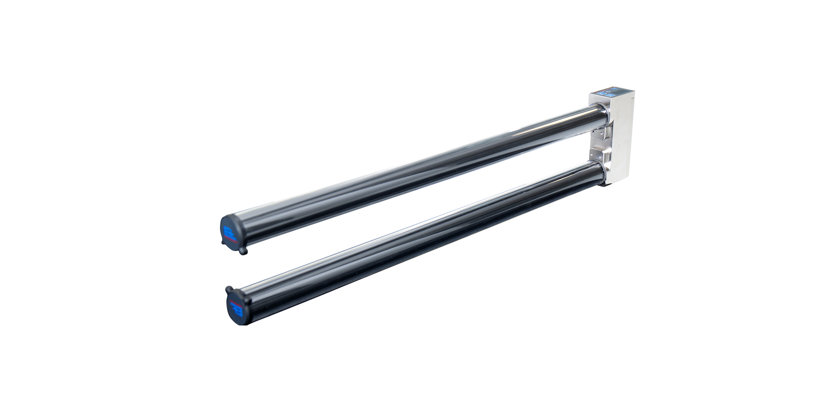
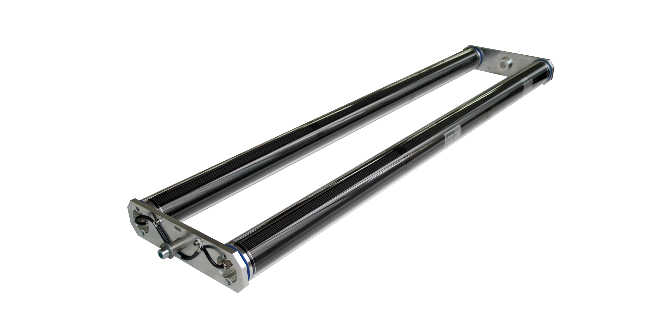
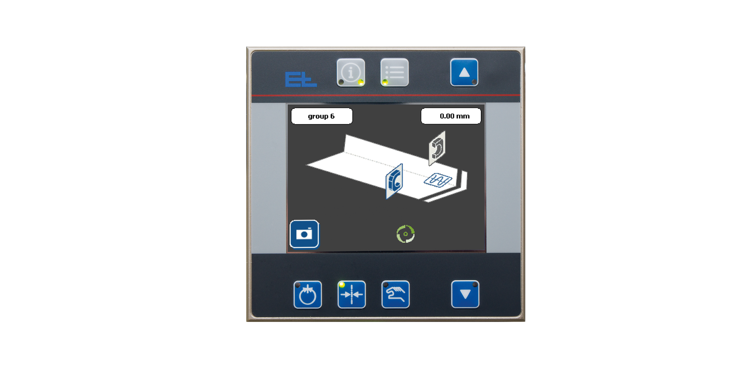
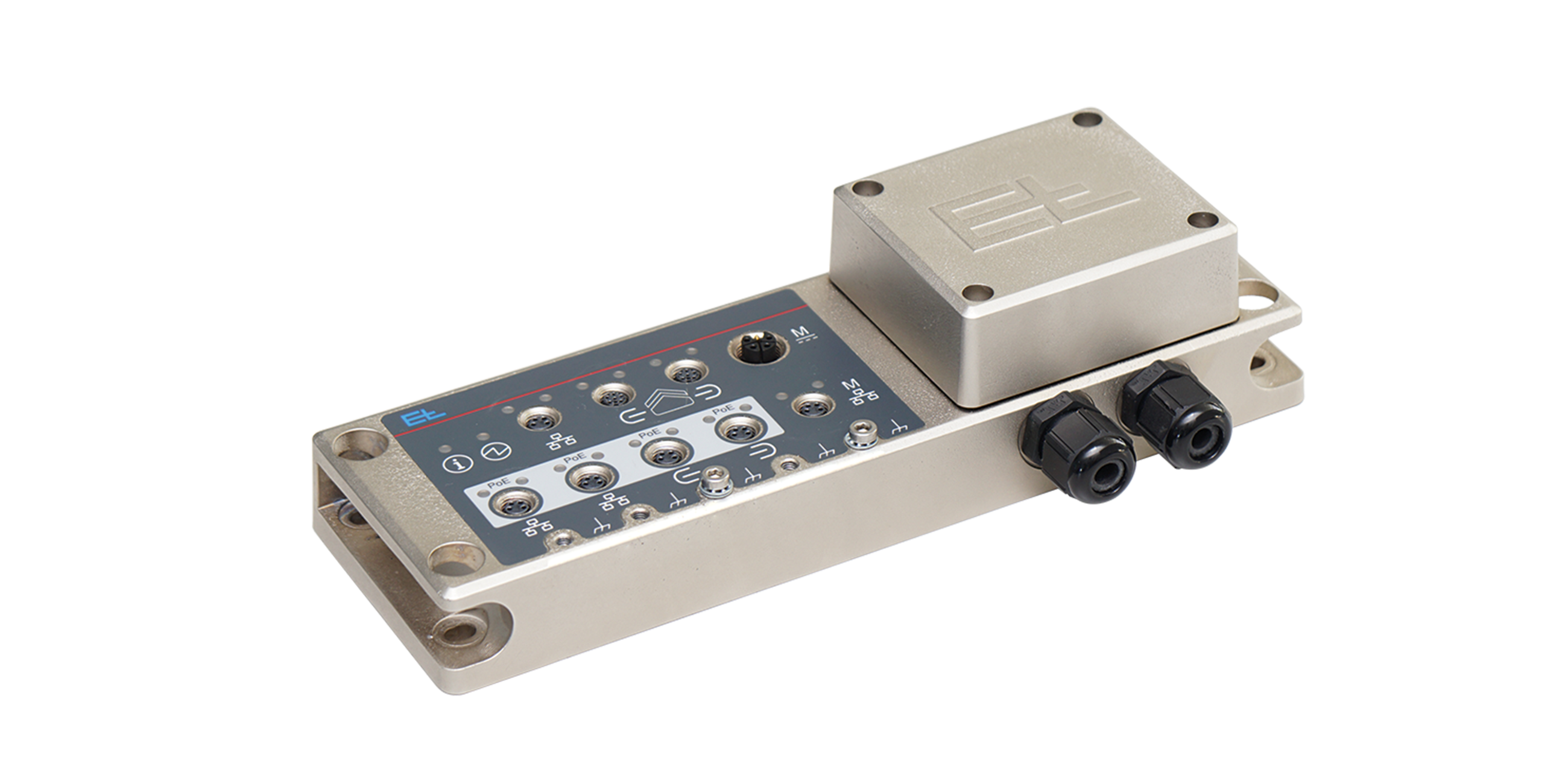
- Description
- Function drawing
Function
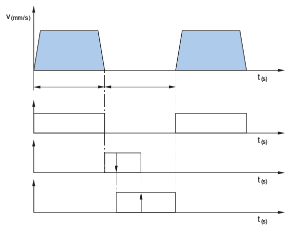
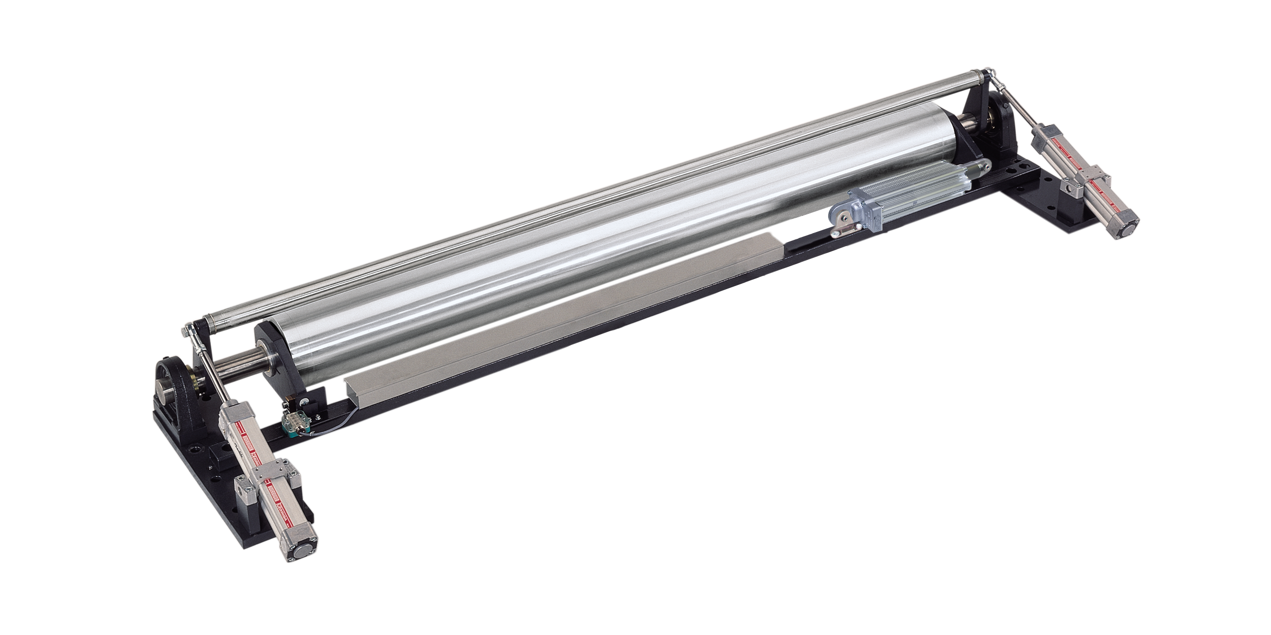
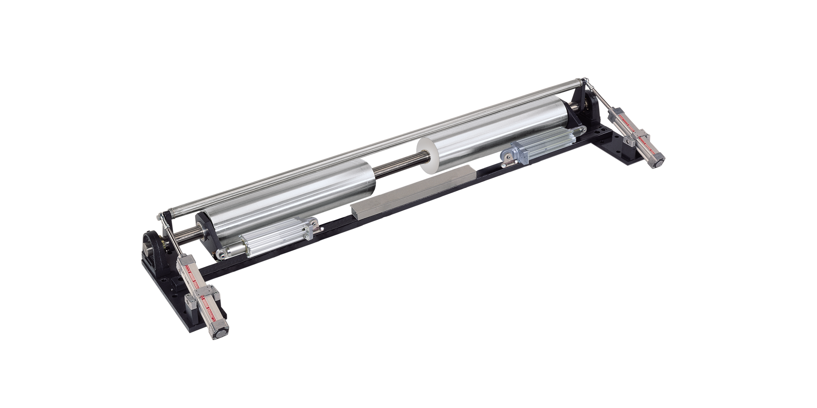
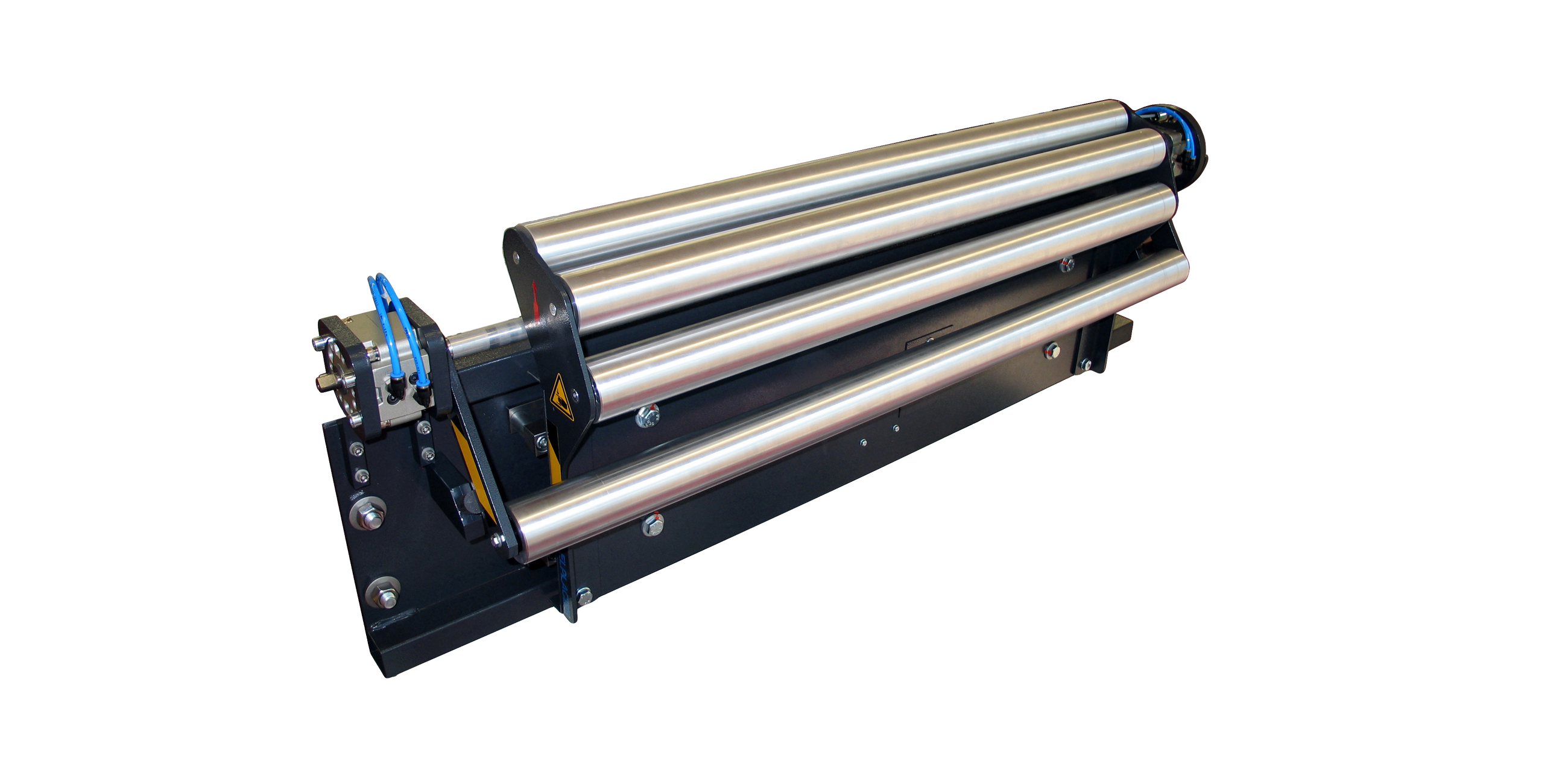
Lateral displacement roller systems ELPLACER position moving webs via the axial movement of the positioning roller. Here, if the positioning roller reaches the end position, the material is lifted by a device, the positioning roller is centered and the web is set back down. As the lateral displacement roller is only used in production systems with cycled operation, the process of lifting the web must always take place during stop times.
Area of use
The area of use extends primarily to tire building machines, because the webs such as the ply and the inner liner are fed in from the loop in cycled operation.
Application
Infeed is always from the loop from the bottom upward and should be kept as short as possible. The sensor should be positioned behind the positioning roller, as near to it as possible. The infeed path should be the equivalent of half to a full web width.
Guiding geometry and longitudinal tension distribution
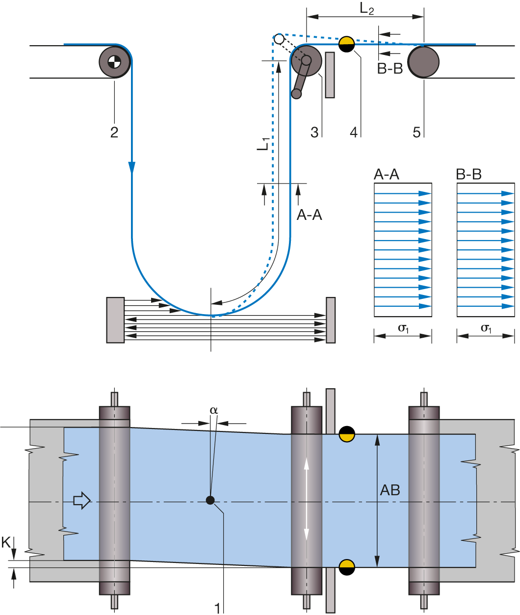
Legend
A-A = Web tension distribution at infeed | B-B = Web tension distribution at exit | K = Web correction | a = Correction angle | σ1 = Basic web tension | AB = Operating width | 1 = Pivot point | 2 = Infeed roller | 3 = Lateral displacement roller | 4 = Sensor | 5 = Locking roller | L1 = Infeed path | L2 = Exit path
Function sequence – lateral displacement roller
